|
<< Prev
[1]
[2]
Next >>
 |
Step 1
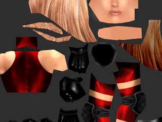
This utility is specifically designed to allow a single image map to contain a collection of sub images.
For example it can be used to design the textures that apply to a character, face clothing etc.
By setting the mapping coordinated in this editor the mesh for the face can be aligned with the part of the
picture representing the face, the torso mesh mapping coordinates can be aligned with the part of the image
representing the torso, and so on.
|
 |
Step 2
To use this editor, begin by selecting all the faces all the faces for which the mapping coordinates are to be changed.
It is necessary to place some form of initial mapping onto these faces and they all must have the same image mapping applied.
(The initial mapping is necessary because, if no mapping coordinates are applied before the map coordinates editor is started
all the vertices in the mesh will be superimposed. (Important: The mesh that appears in this editor is NOT the
mesh that makes up the shape of the object being textured, this mesh is a mesh of surface mapping coordinates.
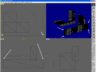
We can start with this arrangements of planar polygons that have an arbitrary map applied and select the indicated vertices.
These apply to the rectangle hightlighted in the 3D window.
|
 |
Step 3
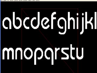
Once the faces (vertices) and map have been selected the mapping coordinates editor appears as a floating window about OpenFX
(on a two screen desktop it can be dragged off onto a second screen.) The editor will show the map image and superimpose on
it a mesh representing the location of the image map coordinates of the vertices within selected faces of the original model mesh.
(Remember, the model structure mesh is three dimensional, wheras the mapping coordinate mesh is two dimensional,
it covers the surface of the selected faces.)
Here we see the picture used for the map with the mapping coordinates of the vertices of the selected mesh drawn in red.
The mapping coordinate editor has a single menu with a number of commands that represent the tools and functions of the editor,
the most commonly used ones also have keyboard equivalents.
By moving the position of the vertices in the above texture mesh map, the part of the map that covers any particular part of the object may be altered.
|
 |
Step 4
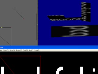
If we reposition the mesh in RED as shown then the rectangle is painted by that part of the map image that lies inside the rectangle.
(As shown.)
We can use the "Update" command to update the mapping and the Select commands to select and de-select the vertices in the mesh. (Note that this
selection only applies to vertices in the "Paint Mapper" is has nothing to do with selected/de-select/hidden vertices in the normal designer!)
Update - Update the mapping coordinates in the model from the data in the Paint Map Coordinates editer (also called the Texture Coordinate Editor (TCE) (After this, the design module and renderer, can be used to inspect the effect of any mapping changes without leaving tje TCE.)
Selection - This menu offers the option to select all or deselect all the vertices in the editor (selected vertices are drawn as larger rectangles, deselected vertices as small rectangles.) The following keyboard equivalents may be used
Select All (ctrl+A)
Deselect All (ctrl+D)
Select (keyboard key S)
When this tool is active you can click and drag a selection box to enclose one or more vertices. Clicking on a single vertex (without dragging) will select it. (or deselect it, if it is already selected.)
|
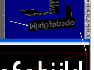 |
Step 5
By rotating, scaling, moving (one vertex or several selected vertices) we can obtain the mapping shown here.
Move (keyboard key M)
Move the selected vertices by clicking and dragging the mouse. If no vertices are selected you can move a single vertex by clicking and dragging it.
Rotate (keyboard key R)
Rotate the selected vertices. Click in the image and drag the mouse (LMB held down.) Rotation is around the point of first click.
Scale (keyboard key X)
Scale the selected vertices. Click and drag the mouse. Scaling takes place at the point of first click.
|
Tutorial written by Stuart
<< Prev
[1]
[2]
Next >>
|